HydraForce Insider Blog

10 Pitfalls To Avoid When Designing Electro-Hydraulic Machines pt. 1

Posted by David Price on Thu, Jan 12, 2012 @ 09:01 AM

I like to tell people that I prefer to learn from someone else’s experience rather than my own because it tends to hurt a lot less. In keeping with that, here are some things I’ve experienced with electro-hydraulics and some simple, easy solutions that will help you take some of the legwork out of developing an EH system.

1. Flashing an ECU on a Machine That’s Running . . .

Read More

Tags: proportional valves, ecu's, electrohydraulic coils

5 Things to Consider When Designing an Electro-Hydraulic Machine

Posted by David Price on Mon, Nov 21, 2011 @ 16:11 PM

Choosing to design a machine with electro-hydraulic control can be a very scary decision for machine manufacturers who are more comfortable with more traditional manual controls.  Here are five things to consider before you take the plunge to an electro-hydraulic system.


1. Consider your operators and technicians.

Switching from manually operated valves to electro-hydraulics is a big step. You are, in a sense, pulling the operator one step further away from the machine. For some people, this is great and they love a color display that allows them to endlessly tweak a hydraulic system without getting soaked with oil. Others enjoy the feel and perceived reliability of a manually configured electronic device system, and find a more traditional technology, such as an analog valve driver that is easily tuned with a screwdriver and trim pots more appealing.

Read More

Tags: cartridge valves, proportional valves, electro-hydraulic equipment, electro-hydraulic control

Right-Size Your Hoses and Pipes To Reduce Pressure Drop in Manifolds

Posted by David Price on Wed, Oct 19, 2011 @ 11:10 AM

When designing a hydraulic system, you want to optimize your design for minimal pressure drop. Savvy system designers have found that using a custom manifold with the right combination of cartridge valves is one way to optimize a system. When using this approach, it is important to correctly size your valves, drillings, and flow paths within the manifold. It is just as important to “right-size” the hydraulic hose and pipe connecting the manifold to the rest of the installation. Hose and tubing need to be the right diameter, length, smoothness and shape to handle the demands of the pressurized hydraulic flow. Undersized hose or tube can cause turbulent flow and excessive heat buildup. Over-sized hose or tube can add cost, size and weight to a system and decrease the rate of flow.

To understand what “right-sizing” means in terms of hydraulic hose and tube, you must first understand the nature of fluid and friction. Whenever fluid flows, there is a loss of mechanical energy to overcome viscous forces within the fluid. In a hydraulic system, this loss is seen as a pressure drop in the direction of flow.

Each component within the hydraulic system will contribute toward the pressure drop, i.e. cartridge valves, tubing, fittings, hoses, filters etc. This lost energy is dissipated as heat energy in the oil.

Frictional losses in pipework are mainly dependent upon:

  • Length of pipe

  • Cross-sectional area of pipe

  • Roughness of pipe surface

  • Number of pipe bends

  • Velocity of flow

  • Viscosity of fluid

The total allowable pressure drop of the hydraulic system must be chosen with care, as the power loss is a product of the system flow rate and pressure drop. This is an efficiency loss that has to be balanced against the cost of larger pipework/hoses and fittings. The wasted energy is dissipated as heat energy in oil, which may lead to cooling problems and shortening of the oil life.

Pressure losses in pipework will depend upon the flow condition. There are two distinct flow conditions: 

  1. Laminar Flow and

  2. Turbulent Flow.

Laminar flow is the condition when the fluid particles travel smoothly in straight lines, the inner-most fluid layer travels at the highest speed and the outer-most layer at the pipe surface doesn’t move, as shown in Figure 1.


Figure 1 – Laminar Flow

Turbulent flow has irregular and chaotic fluid particle motions, such that a thorough mixing of the fluid take place, as shown in Figure 2. Turbulent flow is usually not desirable, as the flow resistance increases and thus the hydraulic losses increase.


Figure 2 – Turbulent Flow

The Right Calculations

To determine the right size of hydraulic piping, you must first do the right calculations for the nature of the hydraulic flow in your system.

Osborne Reynolds discovered that the flow condition depended upon the mean flow velocity, the diameter of the pipe and the kinematic viscosity of the fluid, formula 1.

Re =

4 Q


Π ν d


Formula 1


Q = Flow (m3/s)

d = Pipe internal diameter (m)

ν = Kinematic Viscosity (m2/s)

A Reynolds number of 2000 or under is deemed to be laminar flow. A Reynolds number above 3000 indicates turbulent flow.

Pressure loss in straight pipe can be calculated using Poiseuille’s equation (for laminar flow only). See Formula 2.

ΔP =

128 μ L Q


Π d4


Formula 2


A more general equation used for turbulent flow and laminar flow is D’Arcy equation. See Formula 3.

ΔP =

4f

L


ρ U2


d


2


Formula 3


ΔP = Pressure Loss (Nm-2)

F = Pipe Friction Factor

L = Pipe Length (m)

D = Pipe internal diameter (m)

ρ = fluid density (kg m -3)

U = Fluid mean velocity (ms-1)

The friction factor (f) depends upon the nature of the flow in the pipe. The most convenient form of depicting friction factors are from a Moody Diagram. However for hydraulic systems it is often assumed the pipe conditions are smooth.

A quick and easy and more common method of determining pipe/hose sizing, is to calculate the diameter size based upon recommend fluid velocities. See Table 1.


Line Type


Recommend Mean Velocity m/s

Suction & Case Drain Lines

0.5 to 1.5

Return Lines

2 to 4

Pressure Lines

3 to 5

 Table 1 – Recommend Mean Fluid Velocities

 Based upon using the mean fluid velocities, the appropriate hose/pipe diameter is determined using Formula 4.

 V=

Q x 21.22


d2


Formula 4


Rearrange the formula to get:

d=

Q x 21.22


V


Formula 5


d = Diameter (mm)

Q = Flow (lpm)

V = Fluid Velocity (m/s)

This quick check calculation is useful to ensure that potential pressure drop and energy loss due to hose/pipework is not excessive when designing your manifold installation. For critical long runs of pipe or hose, the pressure losses should be checked using Poiseuille’s or D’Arcy equations as briefly discussed earlier.

Don’t let the wrong size of hydraulic hose or pipe keep your hydraulic system from reaching its maximum efficiency. Do the right calculations, and specify the right size of hydraulic hose and tubing to keep your installation at optimum working pressure.

Click me

Read More

Tags: cartridge valves, hydraulic circuit, hydraulic integrated circuit, manifold design, hydraulic cartridge valves, proper installation of cartridge valves, efficient manifold design

Pitfalls to Avoid When Using an Accumulator in a Hydraulic Manifold

Posted by David Price on Thu, Aug 18, 2011 @ 11:08 AM

Hydraulic accumulators are widely used in mobile systems in bladder, diaphragm and piston formats.  Applications for suspension and ride control have led to an increase in the number of smaller accumulators being mounted directly onto cartridge manifold sub systems. Their many uses include emergency storage, leakage compensation, shock absorption and noise reduction.   While it is always a good idea to consult the manufacturer when integrating an accumulator into a manifold, taking the following parameters into consideration can help you avoid system issues.


Read More

Tags: cartridge valves, Directional Control Valves, pressure control valve, directional control valve, solenoid valves, Accumulator Charging Circuit, unloading pilot valve

5 Things to Consider When Applying Proportional Valves

Posted by David Price on Tue, Jul 05, 2011 @ 12:07 PM

Here at HydraForce our Technical Services department typically receives multiple question daily regarding our Proportional Valves.  Common questions include, "What is the proper dither frequency for a particular proportional valve?' and "What coil should I use with this type of system?".  Following these five simple rules when applying  proportional valves  will prevent field failures, reduce valve instability, and ensure that your system performs as desired without having to reach out to a tech service representative.


1. Applying dither to a valve reduces actuator friction and reduces hysteresis.  A good rule of thumb is to use 70 -250 Hz dither frequency on all SP, ZL, and PV valves (flow and directional control valves), and 200-300 Hz dither frequency on TS Valves (proportional pressure control valves). Otherwise, at lower frequencies the actuator will follow the dither signal and the valve output will appear unstable.

Read More

Tags: proportional valves, Directional Control Valves, pressure control valve, proportional flow control valve, proportional pressure control valve, Proportional Directional Control Valves

When is a pressure reducing valve not a pressure reducer?

Posted by David Price on Tue, May 31, 2011 @ 08:05 AM

Holy turbo chargers!     When it’s a boost valve!

Read More

Tags: cartridge valves, Load Sensing, pressure control valve, logic valves, pressure reducing valves

Using a Proportional Pressure Control as a Directional Control Valve

Posted by David Price on Fri, May 13, 2011 @ 10:05 AM

With Programmable Electronic Controls becoming more prevalent in many hydraulic systems it’s a good time to look at one alternative to Proportional Direction control made possible with the advent of electronic closed loop control.


Read More

Tags: cartridge valves, proportional valves, Directional Control Valves, proportional pressure control valve, solenoid operated four way valves, directional control valve, hydraulic manifold design, ecu's, hydraulic circuit

Making a Case for Hydraulic Manifolds: No More Spaghetti Please

Posted by David Price on Tue, May 03, 2011 @ 10:05 AM

What if I told you I could design a hydraulic system that functions the same or better than your current system, but with less cost, less space requirement, fewer leak points, better appearance and less assembly and installation time? First of all, would you even believe me? Secondly, why aren’t you doing it already?


   Well, everything I said is true. How we achieve a hydraulic system with less cost, less space requirement, fewer leak points, better appearance and less assembly and installation time, is to put it all into a big chunk of aluminum.

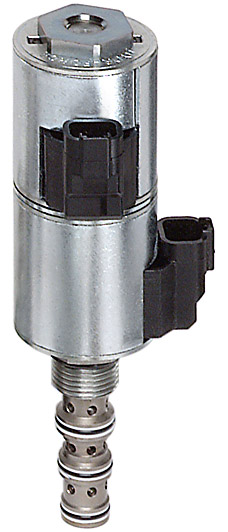
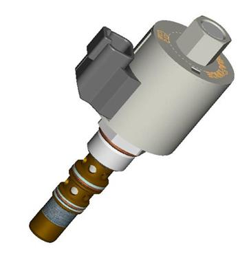
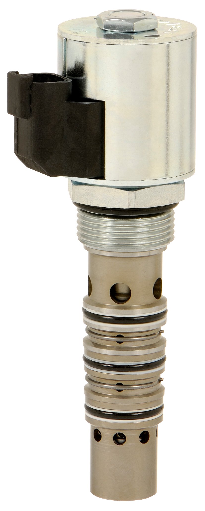
   In the industry, we call a big chunk of aluminum with hydraulic valves in it a “manifold.” HydraForce will sometimes call it a “combination valve.” Whatever you call it, the idea is simple. We take all of the hoses and plumbing that would normally connect separate valve components in a complete system, and we turn those into drillings in that big chunk of aluminum.

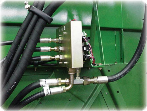
   Let’s talk about why it cost less. If you take ten different hydraulic valves to create a system, you may need thirty hoses and at least as many fittings to connect them all. On top of hose and fittings cost savings, the valves that go in a manifold cost less than separate and independent valves. Each of those individual valves requires its own “block” or “body” anyway. Why have ten of those when you can have one?

   I think it’s easy to see how removing dozens of hoses and fittings and consolidating ten valves into one can save you space. This may not be as much as an issue with industrial applications (depending on the machine), but with a mobile machine, every inch of space is valuable real estate.

  So now that we have fewer hoses, fewer connections and fewer components, we can see how we have reduced the number of points in which you can spring a hydraulic leak. Fewer leaks mean less money dripping away, and a reduced impact of the environment. There are very few hydraulic fluids that are environmentally safe, and the ones that are, are expensive enough to hold on to like a winning lottery ticket.

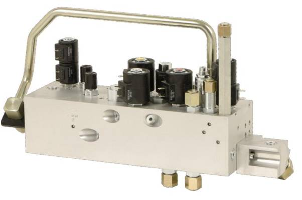
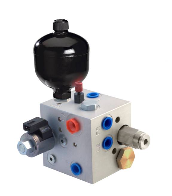
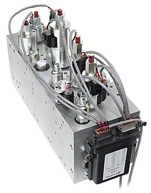
  Another benefit of a manifold design is the attractive appearance. It’s compact and shiny, and can be anodized any colour you wish. They leave you wondering what’s inside, and are great for keeping competitors from seeing how your system is plumbed together. Have a look at the photo on the right; does your hydraulic system look that good?

  Finally, you can’t beat the assembly and installation time of a manifold. Instead of spending hours plumbing separate components together, finding space to mount everything and crimping hoses until the wee hours of the night, you just mount the manifold and hook up your pressure, tank and work lines. Easy peasy, lemon squeezy!

  Manifolds have infinite applications. There are 200 gallon per minute hydraulic presses which use slip in cartridge valves in a manifold, and there are simple one valve custom blocks. One of my customers had just one pressure reducing valve in a custom manifold with a gauge port, and six work ports. This valve didn’t save them any money on the valve itself, but saved them a ton of time during installation and saved hose/fitting costs because it replaced a mess of tees, junctions and connections.

   Another advantage of a cartridge valve and manifold system is that the entire hydraulic circuit can be created and quoted using iDesign software, which is free to anyone who wants it. A system can be created, including positioning of the valves on the block in their 3D model interface. Distributors have access to the pricing function of the software, and we can quote a manifold you designed in seconds. The only real downside is the engineering and manufacturing time. You generally have to plan 6-8 weeks ahead to get a system in your hands.

   If anyone wants the free software, you can download it here, or shoot me an email and I’ll gladly bring a copy out and show you how to use it.

_______________________________________________________

Josh Cosford is a certified hydraulic specialist working in sales for The Fluid Power House (Cambridge) Inc. in Ontario Canada: http://fluidpowerhouse.com/

Contact him at joshc@fluidpowerhouse.com or call (519)-624-7109

He has also contributed articles as a guest writer to Hydraulics and Pneumatics.

Follow him on Twitter: http://twitter.com/#!/FluidPowerTips

Follow him on Faacebook:  http://www.facebook.com/#!/pages/Fluid-Power-Tips-by-Josh-Cosford/173198689366042


Read More

Tags: cartridge valves, benefits of cartridge valves, hydraulic integrated circuit, manifold design

Cartridge Valves Combining Multiple Functions into a Single Cavity

Posted by David Price on Wed, Apr 20, 2011 @ 15:04 PM

A cartridge valve’s function is represented with an ISO standard hydraulic symbol that characterizes the function that the valve performs.  In our many product pages, you can find many unusual valves with very peculiar and complex hydraulic symbols that appear to contain an entire small hydraulic circuit.  In this post I will discuss the principle beyond combining cartridge valves and provide a few practical examples that may help you save money when you are designing a hydraulic circuit.


The idea to develop Multifunction Valves came from our engineers noticing that particular combinations of valves were used over and over again in standard hydraulic circuits.  For example, a 2-way, 2-position SP proportional valve is typically paired with a pressure compensator to provide pressure compensated flow control.  This particular example drove the development of the PV Proportional Flow Control family of valves, which include the flow control and pressure compensator inside the same cartridge.  There are many other multi-function options, including the SPCL, SVCL, SVRV, EPFR, FRRV, and others).

Read More

Tags: cartridge valves, benefits of cartridge valves, Directional Control Valves, proportional flow control valve, hydraulic circuit, manifold design

Conexpo / IFPE HydraForce Post Show Wrap-up

Posted by David Price on Fri, Apr 01, 2011 @ 15:04 PM

Along with showcasing new products, visiting with customers and distributors, and meeting with many potential new customers, ConExpo/IFPE is a time to benchmark how well we are aging.  I enjoyed catching up with friends and former colleagues that I have not seen since 2008 and I hope they think that I am aging gracefully.  Judging from the feedback we received at the booth, HydraForce is aging extremely well.

As Lisa pointed out in a previous post, we skipped the gimmicks this year and went back to the basics, our broad product offering.  That appears to have been the right decision because the show was a great success for HydraForce.  The number of visitors to our boothand their optimism about the future were refreshing.  We were mentioned as a ‘company to watch’ in several pre-show news posts, our new products generated a lot of interest and we received many compliments on the design of our booth, which seemed to work very well for our purposes. 

Read More

Tags: cartridge valves, directional control valve, ecu's, Bridge Circuits, HydraForce

Subscribe by Email

Other related info

Sign up for Product news.

describe the image

describe the image

K  SALES TRAINING Image Library Custom Manifold Consultation resized 156

Follow Me

News Ticker

Click Here to see the latest HydraForce News.

Latest Posts

OTHER RELATED INFO

describe the image

describe the image

K  SALES TRAINING Image Library Custom Manifold Consultation resized 156