A cartridge valve’s function is represented with an ISO standard hydraulic symbol that characterizes the function that the valve performs. In our many product pages, you can find many unusual valves with very peculiar and complex hydraulic symbols that appear to contain an entire small hydraulic circuit. In this post I will discuss the principle beyond combining cartridge valves and provide a few practical examples that may help you save money when you are designing a hydraulic circuit. |
 |
The idea to develop Multifunction Valves came from our engineers noticing that particular combinations of valves were used over and over again in standard hydraulic circuits. For example, a 2-way, 2-position SP proportional valve is typically paired with a pressure compensator to provide pressure compensated flow control. This particular example drove the development of the PV Proportional Flow Control family of valves, which include the flow control and pressure compensator inside the same cartridge. There are many other multi-function options, including the SPCL, SVCL, SVRV, EPFR, FRRV, and others).

Combination of SP and EC to create a PV
The more obvious benefit of combining two or more functions into a single valve is that when you replace two cartridge valves with only one, you save a cavity. Beyond saving a cavity, there are a lot of unexpected benefits that you will discover during the design of the hydraulic schematic. Along with a saved cavity comes an overall reduction of machined aluminum, reduced material space that the cavity and related cross-drills would normally consume in your aluminum or ductile iron block, savings in manifold design time, and the saving of precious machining time on your horizontal or vertical drilling machines.
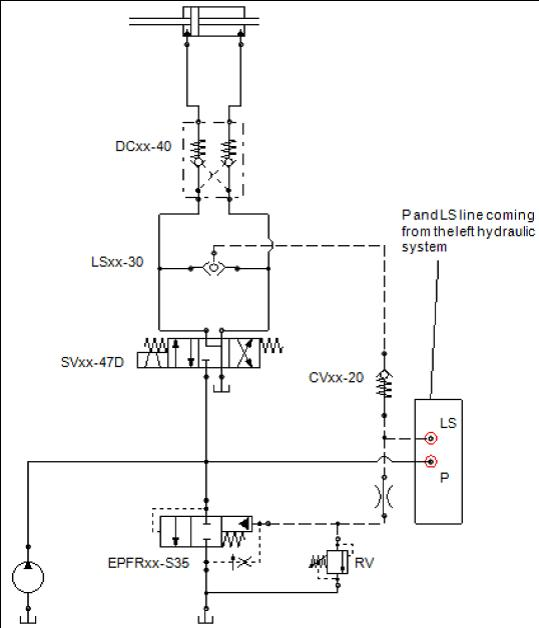
For the first example, let’s look at a single cylinder application, the cylinder is actuated through the use of a 4-way, 3-positions Solenoid valve. The flow used to move the cylinder is regulated via a fixed displacement pump and an EPFRxx-S35 Main Load Sense Pressure Compensator which receive a load sense signal from the LSxx-30 valve.

Though zero leakage is not necessarily needed in these types of circuits, we must use a DC PO-Check valve to split LS line and cylinder pressure when the Solenoid Valve is in neutral. This is the only way to send a 0 bar/psi signal through the LS line when Solenoid Valve is in neutral position.
Now, let’s see this example again using a valve that combines multiple functions into a single cartridge. The first thing you can do is replace the common LS configuration of an SV and LS with a 5-way, 3-Position Solenoid valve that combines the SV and LS valves into a single cartridge. This valve is equipped with a 5th port; this extra port is used to internally sense the downstream LS signal and internally imposes an equivalent restriction. So essentially the valve is driven the same way as the configuration that included the LSxx-30, and you save a three way cavity and all associated cross-drills.

In some applications (ones that do not require a dedicated in-line compensator), to further reduce the number of cavities in this circuit, you can insert the CVD style check valve into the nose of the 5-way cavity machined to containing the SVxx-5x. By doing this, you can avoid the machining of the cavity that would normally be required to for the check valve that connects the pressure line to the main LS line. So in this particular application, introducing a multifunction valve has now saved two cavities, and that is not all….If zero leakage is not strictly needed we can also remove the DC PO-Check valve. In fact, with 5-ways cartridges you can divide or split the LS line and cylinder when the valve is in neutral.
With this feature it is not a big deal if you have pressure inside the cylinder when you are in neutral position because the LS line is separated from the pressure inside the cylinder. Separating the LS signal from the pump is an attractive feature when a cylinder is holding a load or in standby. The reason being, the LS signal will not continually send a high pressure signal to the LS pump, and will not recirculate main pump flow through the cylinder. Whereas if the LS line was connected, you’d recirculate flow through the leg of the circuit, generate heat, and sap horse power from your main engine.
All in all, this particular configuration offer around a 32% cost savings from the original iteration of the circuit.

You can find several other neutral configuration options to build up your system here (on/off version and proportional version). The hydraulic schematic below shows a configuration where the neutral position with the LS connected to the tank.

If both functions do not need to operate simultaneously, you can use this configuration to bleed the LS line through the 5way SPxx-58C which saves you from having to bleed to tank through a flow regulator or orifice.
In Summary:
Multifunction Valves combine two or more functions into a single cartridge, providing easy and smart solution for recurrent hydraulic circuits; learning how to use these valves can produce the benefits below.
- Number of Valves: you can build up your system using fewer components.
- Decrease of External Dimensions: fewer components means fewer cavities and a lighter manifold.
- Costs Benefits: less cavities means less time spent machining the manifold
- Better Control of Tolerances: The controlled tolerances are the combination of the tolerances of both components included inside the multifunction valve; versus multiple components where you’d have to account for a combination of tolerances.
- Design Benefits: multifunction valves make manifold blocks easier to design.
If you need more details shoot me an email
About the Author:

Damiano Roberti is an application engineer for HydraForce Hydraulics Ltd., representing the southeast region of Europe. Damiano resides in Modena, Italy. Contact Damiano


