HydraForce Insider Blog

Making a Case for Hydraulic Manifolds: No More Spaghetti Please

Posted by David Price on Tue, May 03, 2011 @ 10:05 AM

What if I told you I could design a hydraulic system that functions the same or better than your current system, but with less cost, less space requirement, fewer leak points, better appearance and less assembly and installation time? First of all, would you even believe me? Secondly, why aren’t you doing it already?


   Well, everything I said is true. How we achieve a hydraulic system with less cost, less space requirement, fewer leak points, better appearance and less assembly and installation time, is to put it all into a big chunk of aluminum.

   In the industry, we call a big chunk of aluminum with hydraulic valves in it a “manifold.” HydraForce will sometimes call it a “combination valve.” Whatever you call it, the idea is simple. We take all of the hoses and plumbing that would normally connect separate valve components in a complete system, and we turn those into drillings in that big chunk of aluminum.

   Let’s talk about why it cost less. If you take ten different hydraulic valves to create a system, you may need thirty hoses and at least as many fittings to connect them all. On top of hose and fittings cost savings, the valves that go in a manifold cost less than separate and independent valves. Each of those individual valves requires its own “block” or “body” anyway. Why have ten of those when you can have one?

   I think it’s easy to see how removing dozens of hoses and fittings and consolidating ten valves into one can save you space. This may not be as much as an issue with industrial applications (depending on the machine), but with a mobile machine, every inch of space is valuable real estate.

  So now that we have fewer hoses, fewer connections and fewer components, we can see how we have reduced the number of points in which you can spring a hydraulic leak. Fewer leaks mean less money dripping away, and a reduced impact of the environment. There are very few hydraulic fluids that are environmentally safe, and the ones that are, are expensive enough to hold on to like a winning lottery ticket.

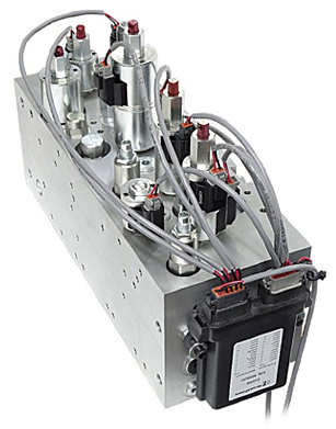
  Another benefit of a manifold design is the attractive appearance. It’s compact and shiny, and can be anodized any colour you wish. They leave you wondering what’s inside, and are great for keeping competitors from seeing how your system is plumbed together. Have a look at the photo on the right; does your hydraulic system look that good?

  Finally, you can’t beat the assembly and installation time of a manifold. Instead of spending hours plumbing separate components together, finding space to mount everything and crimping hoses until the wee hours of the night, you just mount the manifold and hook up your pressure, tank and work lines. Easy peasy, lemon squeezy!

  Manifolds have infinite applications. There are 200 gallon per minute hydraulic presses which use slip in cartridge valves in a manifold, and there are simple one valve custom blocks. One of my customers had just one pressure reducing valve in a custom manifold with a gauge port, and six work ports. This valve didn’t save them any money on the valve itself, but saved them a ton of time during installation and saved hose/fitting costs because it replaced a mess of tees, junctions and connections.

   Another advantage of a cartridge valve and manifold system is that the entire hydraulic circuit can be created and quoted using iDesign software, which is free to anyone who wants it. A system can be created, including positioning of the valves on the block in their 3D model interface. Distributors have access to the pricing function of the software, and we can quote a manifold you designed in seconds. The only real downside is the engineering and manufacturing time. You generally have to plan 6-8 weeks ahead to get a system in your hands.

   If anyone wants the free software, you can download it here, or shoot me an email and I’ll gladly bring a copy out and show you how to use it.

_______________________________________________________

Josh Cosford is a certified hydraulic specialist working in sales for The Fluid Power House (Cambridge) Inc. in Ontario Canada: http://fluidpowerhouse.com/

Contact him at joshc@fluidpowerhouse.com or call (519)-624-7109

He has also contributed articles as a guest writer to Hydraulics and Pneumatics.

Follow him on Twitter: http://twitter.com/#!/FluidPowerTips

Follow him on Faacebook:  http://www.facebook.com/#!/pages/Fluid-Power-Tips-by-Josh-Cosford/173198689366042


Read More

Tags: cartridge valves, benefits of cartridge valves, hydraulic integrated circuit, manifold design

Cartridge Valves Combining Multiple Functions into a Single Cavity

Posted by David Price on Wed, Apr 20, 2011 @ 15:04 PM

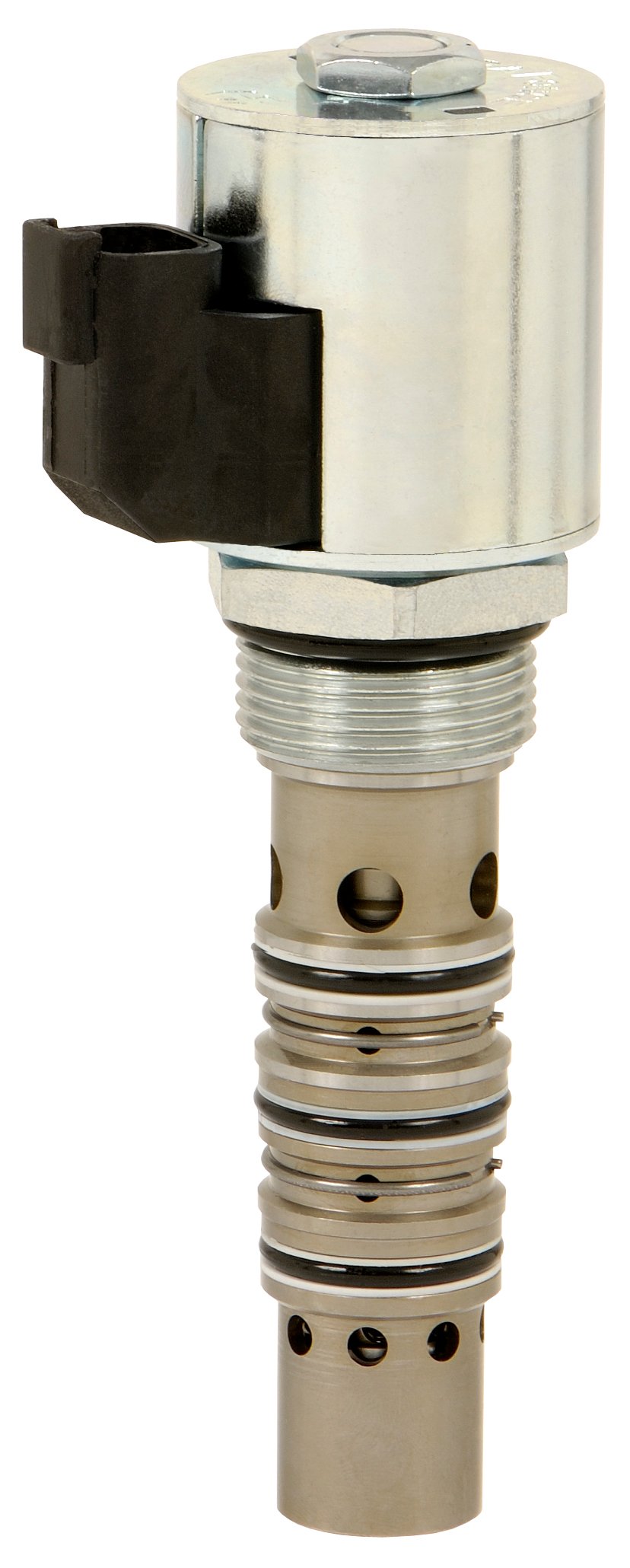
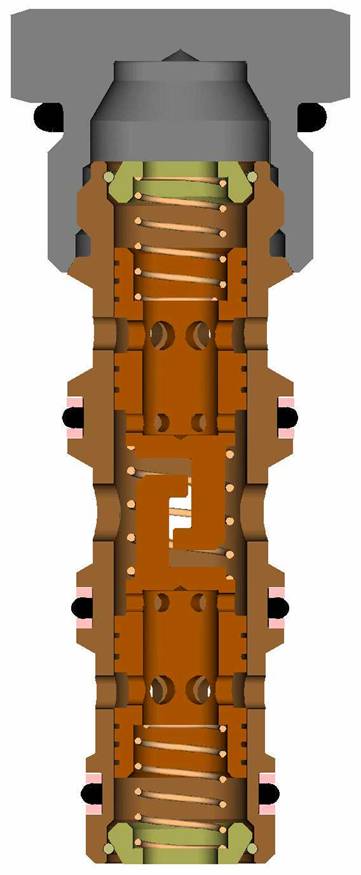
A cartridge valve’s function is represented with an ISO standard hydraulic symbol that characterizes the function that the valve performs.  In our many product pages, you can find many unusual valves with very peculiar and complex hydraulic symbols that appear to contain an entire small hydraulic circuit.  In this post I will discuss the principle beyond combining cartridge valves and provide a few practical examples that may help you save money when you are designing a hydraulic circuit.


The idea to develop Multifunction Valves came from our engineers noticing that particular combinations of valves were used over and over again in standard hydraulic circuits.  For example, a 2-way, 2-position SP proportional valve is typically paired with a pressure compensator to provide pressure compensated flow control.  This particular example drove the development of the PV Proportional Flow Control family of valves, which include the flow control and pressure compensator inside the same cartridge.  There are many other multi-function options, including the SPCL, SVCL, SVRV, EPFR, FRRV, and others).

Read More

Tags: cartridge valves, benefits of cartridge valves, Directional Control Valves, proportional flow control valve, hydraulic circuit, manifold design

Combining Cartridge Valves to Create a Versatile Flow Divider (pt 2)

Posted by David Price on Wed, Mar 30, 2011 @ 13:03 PM

Last time we discussed how to make a flow divider with separate cartridges.  If this was of interest the following goes a little deeper into this subject and shows how to maximize the versatility and address general flow divider issues.

First off, it’s worth noting that unlike Flow Sharing the pump itself does not have to be load sensed if all flow is to be utilized in a stand-alone circuit.

a)
Read More

Tags: cartridge valves, proportional valves, benefits of cartridge valves, Flow Divider, flow regulator, flow control valve, needle valves

Combining Cartridge Valves to Create a Versatile Flow Divider

Posted by David Price on Thu, Mar 17, 2011 @ 14:03 PM

Are you looking for an alternative for your Flow Divider circuit that will address the issues of multiple division, irregular percentage splits, adjustable ratios, inlet flow variance versus accuracy and pressure drop?  If so, an alternative works for dividing pump flow only.  If you need combining too, you might have to stick with the traditional flow divider / combiner (or read next week’s article to see a combining solution). 

Flow dividing circuits are used in many mobile applications to make full use of a varying input flow.  Spool type dividers can be integrated into manifolds and are available in many sizes and fixed ratios.  Although they can be cascaded, they are individually limited to a 2-way split.  The valve ratios (i.e. 50/50 or 20/80) are fixed and factory preset by varying each spools flow specifications.

Read More

Tags: cartridge valves, proportional valves, Load Sensing, Cartridge Valve Pressure Compensators, benefits of cartridge valves, Flow Divider, hydraulic manifold design, pressure compensators

8 Ways To Use Load Sensing Cartridge Valves

Posted by David Price on Thu, Mar 10, 2011 @ 10:03 AM

While there are many uses for L.S. priority valves, typically they are used to provide priority flow and/or pressure to certain components or functions depending on need. One of the most common uses is to apply them with L.S. steering orbitals.
The two most common types of L.S. steering orbitals (Static and Dynamic) are shown below. We use a static L.S. priority valve (ECxx-42) with a static steering orbital and a dynamic L.S. priority valve (ECxx-43) with a dynamic steering orbital. Notice the direction of the sense flow.

Load Sense Priority Valve

Static Steering Unit

Static Steering

In a static steering system, the sense flow goes from the steering orbital to the EC valve. The faster you turn the steering wheel, the more flow comes out the work ports.

There are several variable orifices in the steering orbital, which open and close proportionally based on how fast you spin the wheel. In neutral, the sense pressure vents to tank through the steering unit.


Dynamic Steering Unit

Dynamic Steering

In a dynamic steering system, the sense flow goes from the EC valve to the steering orbital and back to tank through the variable bleed orifice in the steering orbital.

Turning the steering wheel opens the work ports and closes the bleed-off orifice, thus building pressure in the sense line pushing on the EC spool. This directs more oil to the orbital the faster you spin the wheel.


Most Steering Circuits Utilizing Orbitals Use a Dynamic Setup

Steering Circuits

Since the steering unit is really just a rotary style variable orifice, using a pre-compensator in conjunction with it makes the steering function compensated. With a given steering RPM, the flow will remain constant regardless of varying load pressure.

The boost orifice needs to be located in the shown position to prevent slow movement of the EC spool when the RV opens, thus preventing a pressure spike.

The objective is for the steering to work perfectly with as little pressure drop as possible, however sometimes we need to fine tune the responsiveness or the maximun steering flow by tweaking a few things.


Ways to Fine-Tune the Circuit to Optimize Steering Performance

Optimize Steering

The pressure differential between the EC valve and the L.S. port of the steering unit is called the margin pressure. This pressure differential controls the responsiveness and the maximum steering flow. This is determined by a combination of the bias spring of the EC and boost orifice.

The dynamic L.S. priority valves have two orifices in the spool, one for damping (PP), and the other for feeding (DS) oil to the orbital. The pilot flow to the L.S. port of the steering unit is determined by the spring value and the feed orifice. The spring value is typically either 80 psi or 100 psi, while the orifice is typically between 0.020" and 0.031" Dia., depending on which size EC valve you are using.

You can create any margin pressure you want by simply increasing or decreasing the size of the boost orifice. The smaller the orifice, the higher the margin pressure.

Pressure drop data from a steering unit catalog will help determine what is required to achieve the flow you need. However, the responsiveness or optimum feel is typically determined by an expert operator. By increasing or decreasing the boost orifice, you will be able to fine-tune the responsiveness or feel of the steering wheel.

An increase or decrease of as little as 0.002" Dia. can make a huge difference in the steering feel. Margin pressure that is too low will result in steering that is slow and sluggish. Margin pressure too high will result in jerky steering.

 
There are many other uses for L.S. Priority Valves as shown below:
 

Proportional Steering and On/Off Lift Circuit

Proportional Steering

It is common to use proportional valves instead of steering orbitals to steer many types of equipment. This circuit simply gives priority to steering while allowing the excess flow to lift and lower a cylinder. The EC valve not only gives priority to steering, it also compensates the proportional valve so the same current value will achieve the same flow regardless of load.


Priority Valve Working with Manual Valve

Priority Valve with Manual Valve

It is becoming more common to use an EC valve mounted to the inlet of a manual valve to give priority to certain functions while also limiting the maximum flow and pressure to those functions.


Typical Priority-on-Demand
Flow Control Circuit

Flow Control

Most uses of the L.S. Priority Valves are for flow control. By sensing downstream of a fixed or variable orifice, you can compensate the circuit. The needle valve shown above could be any one of a number of components such as a ball valve, proportional valve, on/off valve or a simple orifice.


Pressure Control Valve

Pressure Control

Many people don't realize you can use an
ECxx-42 or ECxx-43 to create a pressure control. Think of this as a pressure reducing valve with an excess flow port. The valve will modulate to maintain the spring value in the priority (CF) leg regardless of flow and/or the downstream pressure and flow in the bypass leg. Higher spring pressures can be achieved by using an ECxx-43 and boosting the sense line with an orifice or relief valve.


Do you have another Priority Valve Application?
Do you have any questions about any of the circuits I describe here?
Shoot me an email if you’d like to share your application or ask a question.


About the Author:

Scott Parker is a Senior Application Engineer at HydraForce.
He’s been developing Hydraulic Systems for 20 years. Contact Scott


Read More

Tags: cartridge valves, Load Sensing, Priority Valves, Hydraulic Steering Circuits, Load Sense Priority Valves, benefits of cartridge valves, pressure control valve

3 Overlooked Benefits of Cartridge Valves

Posted by David Price on Wed, Mar 09, 2011 @ 10:03 AM

Most of you reading this know the common benefits of hydraulic cartridge valves (click here for an excellent refresher). However, there are several key benefits routinely overlooked or misunderstood throughout the industry. HydraForce has dedicated significant efforts to innovation in cartridge valve technology — including the consolidation of multiple valve functions into a single cartridge, higher pressure and flow ratings, and improved machine control solutions.


Most of you reading this know the common benefits of hydraulic cartridge valves (click here for an excellent refresher). However, there are several key benefits routinely overlooked or misunderstood throughout the industry. HydraForce has dedicated significant efforts to innovation in cartridge valve technology — including the consolidation of multiple valve functions into a single cartridge, higher pressure and flow ratings, and improved machine control solutions.

Now, let’s talk about the benefits that go along with these improvements:

1. Performance

Traditionally, directional control functions were not considered a strong suit of cartridge valves. When searching online for a supplier of Directional Control Valves, a Google search will scarcely yield a "Cartridge Valve" return in the results. This has mostly to do with the limited flow capabilities of early cartridge valves. However, a lot has changed over the years, and today’s market could not be more ripe with Directional / Stack valve alternatives

The bridge circuit below (named for its hydraulic similarities to the electronic "Wheatstone Bridge") has several key attributes which make it ideal for directional control. For starters, by having individual cartridge valves at the inlet of your A and B ports you get the distinct advantage of both meter-in and meter-out capabilities. Another advantage of this circuit is the ability to scale the appropriate cartridge valves for optimal flow. Other benefits include low-leakage poppet-type valving, lighter housing weight and the ability to achieve float or motor functions.


View/Download Directional Bridge Circuit graphic as:
PDF file
(127 KB) | DXF file (201 KB)

HydraForce i-Design HF3D file (zipped 29 KB)


While we can’t deny there are inherent advantages of traditional directional stack valves, there are good reasons to consider this cartridge-valve alternative when designing your machine. 

Read More

Tags: proportional valves, benefits of cartridge valves, Directional Control Valves, cartridge valve serviceability, Directional Stack Valve Alternatives, Bridge Circuits

Subscribe by Email

Other related info

Sign up for Product news.

describe the image

describe the image

K  SALES TRAINING Image Library Custom Manifold Consultation resized 156

Follow Me

News Ticker

Click Here to see the latest HydraForce News.

Latest Posts

OTHER RELATED INFO

describe the image

describe the image

K  SALES TRAINING Image Library Custom Manifold Consultation resized 156