HydraForce Insider Blog

Right-Size Your Hoses and Pipes To Reduce Pressure Drop in Manifolds

Posted by David Price on Wed, Oct 19, 2011 @ 11:10 AM

When designing a hydraulic system, you want to optimize your design for minimal pressure drop. Savvy system designers have found that using a custom manifold with the right combination of cartridge valves is one way to optimize a system. When using this approach, it is important to correctly size your valves, drillings, and flow paths within the manifold. It is just as important to “right-size” the hydraulic hose and pipe connecting the manifold to the rest of the installation. Hose and tubing need to be the right diameter, length, smoothness and shape to handle the demands of the pressurized hydraulic flow. Undersized hose or tube can cause turbulent flow and excessive heat buildup. Over-sized hose or tube can add cost, size and weight to a system and decrease the rate of flow.

To understand what “right-sizing” means in terms of hydraulic hose and tube, you must first understand the nature of fluid and friction. Whenever fluid flows, there is a loss of mechanical energy to overcome viscous forces within the fluid. In a hydraulic system, this loss is seen as a pressure drop in the direction of flow.

Each component within the hydraulic system will contribute toward the pressure drop, i.e. cartridge valves, tubing, fittings, hoses, filters etc. This lost energy is dissipated as heat energy in the oil.

Frictional losses in pipework are mainly dependent upon:

  • Length of pipe

  • Cross-sectional area of pipe

  • Roughness of pipe surface

  • Number of pipe bends

  • Velocity of flow

  • Viscosity of fluid

The total allowable pressure drop of the hydraulic system must be chosen with care, as the power loss is a product of the system flow rate and pressure drop. This is an efficiency loss that has to be balanced against the cost of larger pipework/hoses and fittings. The wasted energy is dissipated as heat energy in oil, which may lead to cooling problems and shortening of the oil life.

Pressure losses in pipework will depend upon the flow condition. There are two distinct flow conditions: 

  1. Laminar Flow and

  2. Turbulent Flow.

Laminar flow is the condition when the fluid particles travel smoothly in straight lines, the inner-most fluid layer travels at the highest speed and the outer-most layer at the pipe surface doesn’t move, as shown in Figure 1.


Figure 1 – Laminar Flow

Turbulent flow has irregular and chaotic fluid particle motions, such that a thorough mixing of the fluid take place, as shown in Figure 2. Turbulent flow is usually not desirable, as the flow resistance increases and thus the hydraulic losses increase.


Figure 2 – Turbulent Flow

The Right Calculations

To determine the right size of hydraulic piping, you must first do the right calculations for the nature of the hydraulic flow in your system.

Osborne Reynolds discovered that the flow condition depended upon the mean flow velocity, the diameter of the pipe and the kinematic viscosity of the fluid, formula 1.

Re =

4 Q


Π ν d


Formula 1


Q = Flow (m3/s)

d = Pipe internal diameter (m)

ν = Kinematic Viscosity (m2/s)

A Reynolds number of 2000 or under is deemed to be laminar flow. A Reynolds number above 3000 indicates turbulent flow.

Pressure loss in straight pipe can be calculated using Poiseuille’s equation (for laminar flow only). See Formula 2.

ΔP =

128 μ L Q


Π d4


Formula 2


A more general equation used for turbulent flow and laminar flow is D’Arcy equation. See Formula 3.

ΔP =

4f

L


ρ U2


d


2


Formula 3


ΔP = Pressure Loss (Nm-2)

F = Pipe Friction Factor

L = Pipe Length (m)

D = Pipe internal diameter (m)

ρ = fluid density (kg m -3)

U = Fluid mean velocity (ms-1)

The friction factor (f) depends upon the nature of the flow in the pipe. The most convenient form of depicting friction factors are from a Moody Diagram. However for hydraulic systems it is often assumed the pipe conditions are smooth.

A quick and easy and more common method of determining pipe/hose sizing, is to calculate the diameter size based upon recommend fluid velocities. See Table 1.


Line Type


Recommend Mean Velocity m/s

Suction & Case Drain Lines

0.5 to 1.5

Return Lines

2 to 4

Pressure Lines

3 to 5

 Table 1 – Recommend Mean Fluid Velocities

 Based upon using the mean fluid velocities, the appropriate hose/pipe diameter is determined using Formula 4.

 V=

Q x 21.22


d2


Formula 4


Rearrange the formula to get:

d=

Q x 21.22


V


Formula 5


d = Diameter (mm)

Q = Flow (lpm)

V = Fluid Velocity (m/s)

This quick check calculation is useful to ensure that potential pressure drop and energy loss due to hose/pipework is not excessive when designing your manifold installation. For critical long runs of pipe or hose, the pressure losses should be checked using Poiseuille’s or D’Arcy equations as briefly discussed earlier.

Don’t let the wrong size of hydraulic hose or pipe keep your hydraulic system from reaching its maximum efficiency. Do the right calculations, and specify the right size of hydraulic hose and tubing to keep your installation at optimum working pressure.

Click me

Read More

Tags: cartridge valves, hydraulic circuit, hydraulic integrated circuit, manifold design, hydraulic cartridge valves, proper installation of cartridge valves, efficient manifold design

Making a Case for Hydraulic Manifolds: No More Spaghetti Please

Posted by David Price on Tue, May 03, 2011 @ 10:05 AM

What if I told you I could design a hydraulic system that functions the same or better than your current system, but with less cost, less space requirement, fewer leak points, better appearance and less assembly and installation time? First of all, would you even believe me? Secondly, why aren’t you doing it already?


   Well, everything I said is true. How we achieve a hydraulic system with less cost, less space requirement, fewer leak points, better appearance and less assembly and installation time, is to put it all into a big chunk of aluminum.

   In the industry, we call a big chunk of aluminum with hydraulic valves in it a “manifold.” HydraForce will sometimes call it a “combination valve.” Whatever you call it, the idea is simple. We take all of the hoses and plumbing that would normally connect separate valve components in a complete system, and we turn those into drillings in that big chunk of aluminum.

   Let’s talk about why it cost less. If you take ten different hydraulic valves to create a system, you may need thirty hoses and at least as many fittings to connect them all. On top of hose and fittings cost savings, the valves that go in a manifold cost less than separate and independent valves. Each of those individual valves requires its own “block” or “body” anyway. Why have ten of those when you can have one?

   I think it’s easy to see how removing dozens of hoses and fittings and consolidating ten valves into one can save you space. This may not be as much as an issue with industrial applications (depending on the machine), but with a mobile machine, every inch of space is valuable real estate.

  So now that we have fewer hoses, fewer connections and fewer components, we can see how we have reduced the number of points in which you can spring a hydraulic leak. Fewer leaks mean less money dripping away, and a reduced impact of the environment. There are very few hydraulic fluids that are environmentally safe, and the ones that are, are expensive enough to hold on to like a winning lottery ticket.

  Another benefit of a manifold design is the attractive appearance. It’s compact and shiny, and can be anodized any colour you wish. They leave you wondering what’s inside, and are great for keeping competitors from seeing how your system is plumbed together. Have a look at the photo on the right; does your hydraulic system look that good?

  Finally, you can’t beat the assembly and installation time of a manifold. Instead of spending hours plumbing separate components together, finding space to mount everything and crimping hoses until the wee hours of the night, you just mount the manifold and hook up your pressure, tank and work lines. Easy peasy, lemon squeezy!

  Manifolds have infinite applications. There are 200 gallon per minute hydraulic presses which use slip in cartridge valves in a manifold, and there are simple one valve custom blocks. One of my customers had just one pressure reducing valve in a custom manifold with a gauge port, and six work ports. This valve didn’t save them any money on the valve itself, but saved them a ton of time during installation and saved hose/fitting costs because it replaced a mess of tees, junctions and connections.

   Another advantage of a cartridge valve and manifold system is that the entire hydraulic circuit can be created and quoted using iDesign software, which is free to anyone who wants it. A system can be created, including positioning of the valves on the block in their 3D model interface. Distributors have access to the pricing function of the software, and we can quote a manifold you designed in seconds. The only real downside is the engineering and manufacturing time. You generally have to plan 6-8 weeks ahead to get a system in your hands.

   If anyone wants the free software, you can download it here, or shoot me an email and I’ll gladly bring a copy out and show you how to use it.

_______________________________________________________

Josh Cosford is a certified hydraulic specialist working in sales for The Fluid Power House (Cambridge) Inc. in Ontario Canada: http://fluidpowerhouse.com/

Contact him at joshc@fluidpowerhouse.com or call (519)-624-7109

He has also contributed articles as a guest writer to Hydraulics and Pneumatics.

Follow him on Twitter: http://twitter.com/#!/FluidPowerTips

Follow him on Faacebook:  http://www.facebook.com/#!/pages/Fluid-Power-Tips-by-Josh-Cosford/173198689366042


Read More

Tags: cartridge valves, benefits of cartridge valves, hydraulic integrated circuit, manifold design

Cartridge Valves Combining Multiple Functions into a Single Cavity

Posted by David Price on Wed, Apr 20, 2011 @ 15:04 PM

A cartridge valve’s function is represented with an ISO standard hydraulic symbol that characterizes the function that the valve performs.  In our many product pages, you can find many unusual valves with very peculiar and complex hydraulic symbols that appear to contain an entire small hydraulic circuit.  In this post I will discuss the principle beyond combining cartridge valves and provide a few practical examples that may help you save money when you are designing a hydraulic circuit.


The idea to develop Multifunction Valves came from our engineers noticing that particular combinations of valves were used over and over again in standard hydraulic circuits.  For example, a 2-way, 2-position SP proportional valve is typically paired with a pressure compensator to provide pressure compensated flow control.  This particular example drove the development of the PV Proportional Flow Control family of valves, which include the flow control and pressure compensator inside the same cartridge.  There are many other multi-function options, including the SPCL, SVCL, SVRV, EPFR, FRRV, and others).

Read More

Tags: cartridge valves, benefits of cartridge valves, Directional Control Valves, proportional flow control valve, hydraulic circuit, manifold design

Come See HydraForce at Conexpo / ConAgg 2011

Posted by David Price on Thu, Mar 10, 2011 @ 15:03 PM

Are you headed to Las Vegas for Conexpo- Con/Agg 2011 - Con/Agg 2011?  As you already know, anyone who is anyone will be at this event!  HydraForce is no exception; we are located at BOOTH S-15729.  After coming home from our most successful show yet, Bauma China, we are ready for IFPE 2011.

We are going back to the basics with our show setup and layout.   Our most successful shows have been when we highlight and focus on what we do best – innovation.  Visit us at Booth S-15729 and we will be happy to show you why we are the industry leader.  

At the 2011 Conexpo- Con/Agg 2011 - Con/Agg 2011 HydraForce will have 5 stations set up highlighting new product developments.  Did you know that even during the poor economy HydraForce continued investing in R & D?  In fact, we spent the same dollar amount on R & D during 2009 and 2010 as we had in 2008, even though we all know the sales were down significantly during these years.  That should speak volumes to our commitment to innovation.

One of the stations will highlight our new CoreTek Controller product line.  Our customers wanted controllers with an open programming interface and plenty of power for driving valves, well now you do.  The CoreTek controller line uses the CoDeSys software platform, making programming simple and in your control with zero annual licensing fees!  Four controllers with varying I/O configurations are available, and as your feedback dictated, the controllers are CE rated to ISO 14982.   

Station 2 will highlight of our new valve innovations.  Maybe you already knew about our technology for combining two hydraulic functions in one cartridge.  At Conexpo- Con/Agg 2011 we’ll be introducing valves with 3 functions in a single cartridge!  At IFPE 2008, we introduced a handful of these cartridges and we have continued the past 3 years to develop more.  These cartridges can reduce the cost of hydraulic integrated circuits, making manifolds smaller and lighter.  Thanks to your help and ideas, these types of valves have really taken off in the market.  So, if you are thinking about updating your machine designs, it’s time to take a look at HydraForce and these revolutionary new cartridges.

We are also pleased to show off our full line of proportional valves.  HydraForce is the largest supplier of proportional valves, and we continue to add products regularly.  The innovation of bringing 2 functions, or some cases, 3 functions into one cartridge has migrated to our proportional line.  The latest valve series is actually pulling double duty at the show.  It is not only a proportional directional valve (which doubles as flow control), but also a double blocking valve with a built in load sense port and reverse flow check.  These new proportional double blocking valves with built in load sense can be used to create some unique and cost effective circuit designs, which, incidentally, will be unveiled at this years show.

I mentioned unique and cost effective circuits using this new valve technology, however I don’t think I want to let this cat out of the bag just yet!  You will just have to come see for yourself. Let’s just say we are pretty sure HydraForce will soon be able to break into the high flow proportional directional sectional stack valve market!  So if haven’t looked at, or thought of HydraForce for your proportional sectional stack valve applications, it’s time you do!

The new green movement is creating a global economy where OEM’s are looking to make their equipment, faster, cheaper, and greener.  More and more we see the development of smaller more compact equipment designed to do the work of older, larger, less green equipment.  In order to get the power needed, system pressures are increasing and things like cylinders and actuators are getting smaller.  HydraForce has seen the need for a reliable, high cycle, high-pressure cartridge valve line, and it is now in full development!  The HyPerformance cartridge valve program that will consist of a full offering of our cartridge valves (we hope it will take the market by storm).  These new HyPerformance valves are continuous duty rated to over 5000 PSI/350 Bar and have 10% duty cycle rating to over 6000 PSI/ 420 Bar.  There are a few patent pending technologies at play here with this new series of valves.  One of these patents pertains to the new solenoid tube design. Yes, even the solenoid tubes are tested and rated to these pressures.  Over 90 valves are released and ready for your high-pressure application, come see this exciting new series of HyPerformance valves.

In addition to all of the new products, we will have an i-Design station where you can learn how to use the tool, and learn more about the various new features of the tool.  i-Design experts will be there to answer your questions and listen to your feedback.  If you’d like to get a head start on using i-Design, you can download the software now by clicking here.  We will also have copies of this free circuit design software on hand.  

Other news and note worthy information is the new and improved E-Coil that will soon be available with the ASTM B117 960 hour salt spray specification.  

Lastly, we have – FINALLY – created a Condensed HydraForce Catalog, one that will not dislocate your shoulder if you try to carry it in your brief case.  Swing by our booth to register for your own copy

The IFPE is always a great way to re-connect and see what’s new and old (~me~).  For those of you who know me, I’ve been at everyone one of these since I started here 16 years ago. As usual, I am looking forward to it: seeing some old friends and associates and hopefully meeting some new ones, so swing by and say Hi

_______________________________________________

About the Author:

Lisa DeBenedetto is a Regional Manager at HydraForce with more than 20 years of hydraulic experience. She has been with HydraForce for over 16 years. Contact Lisa

Read More

Tags: cartridge valves, proportional valves, Bridge Circuits, HydraForce, manifold design, Hydraulics Industry, solenoid valves, manifold design software, multi-function cartridge valves

Leveraging Proportional Valve Technology

Posted by David Price on Thu, Mar 10, 2011 @ 10:03 AM

Are You Ready to Move from On/Off to Proportional Control but your Customers Aren't?

This is an ongoing battle for most of us. There is some pretty slick new technology out there that will make most equipment more efficient, safer, lighter, smaller, and even greener, but getting the end users and industries to adapt is quite another issue.

One of the simplest moves in this area from a valve standpoint is moving from bang/bang or On/Off control to proportional control. I use the word “simplest” quite loosely here, so let me explain.

There are still lots of industries out there where Manual Levers are KING and getting operators to move to joysticks, control panels, buttons and knobs is an uphill battle. I am not sure we will ever get away from the manual levers, but for those of you whose equipment is already electro-hydraulic, moving from on/off to proportional can be quite simple.

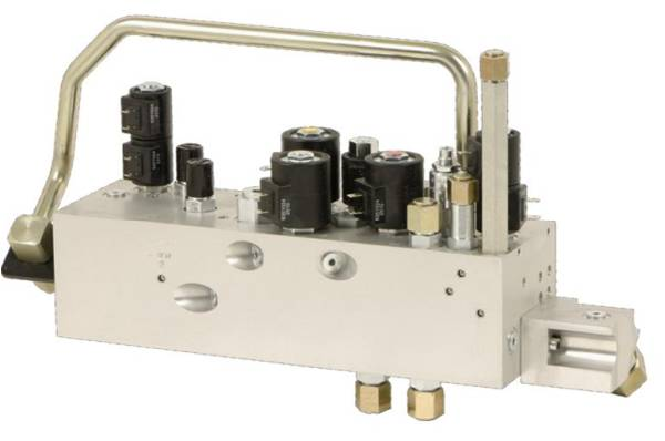
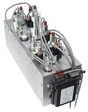
When looking at creating custom mono-blocks or custom manifolds, we all know that quantity plays a role in the cost-effectiveness of this option. So, if you needed one manifold for on/off and one for proportional, going the custom, mono-block option is probably not feasible. For example, if the majority of your machines use on/off, while only a few select customers see the advantages of proportional, designing the machine to accommodate two different custom manifolds is just not practical. But what if you could design one custom manifold block that can be either on/off or proportional by switching out the on/off valves with the equivalent proportional valves? In other words, you could use the same manifold block for 100% of your applications even though some of those applications are on/off and some are proportional. I will review an example and discuss a little about the cost implications, but for the most part, you will see that this option is very feasible.

Let’s take a sweeper application. In most cases on/off control of the brooms is sufficient and probably an industry standard, so most operators are used to it and therefore prefer it. However, having proportional broom control offers clear advantages, such as: slowing down the brooms for certain surfaces which could extend broom life, as well as having the option of controlling broom speeds for specific debris, which would improve productivity. A very cost-effective solution can be created by designing a custom manifold that uses on/off valves for the majority of users, but has the proportional option for the progressive users just by swapping out a cartridge. (Electrical scheme notwithstanding but I will discuss this later.) So, as the sweeper OEMs push to move their customers and industry to proportional, the packaging of the hydraulic valve system doesn’t have to change, keeping overall cost to a minimum.

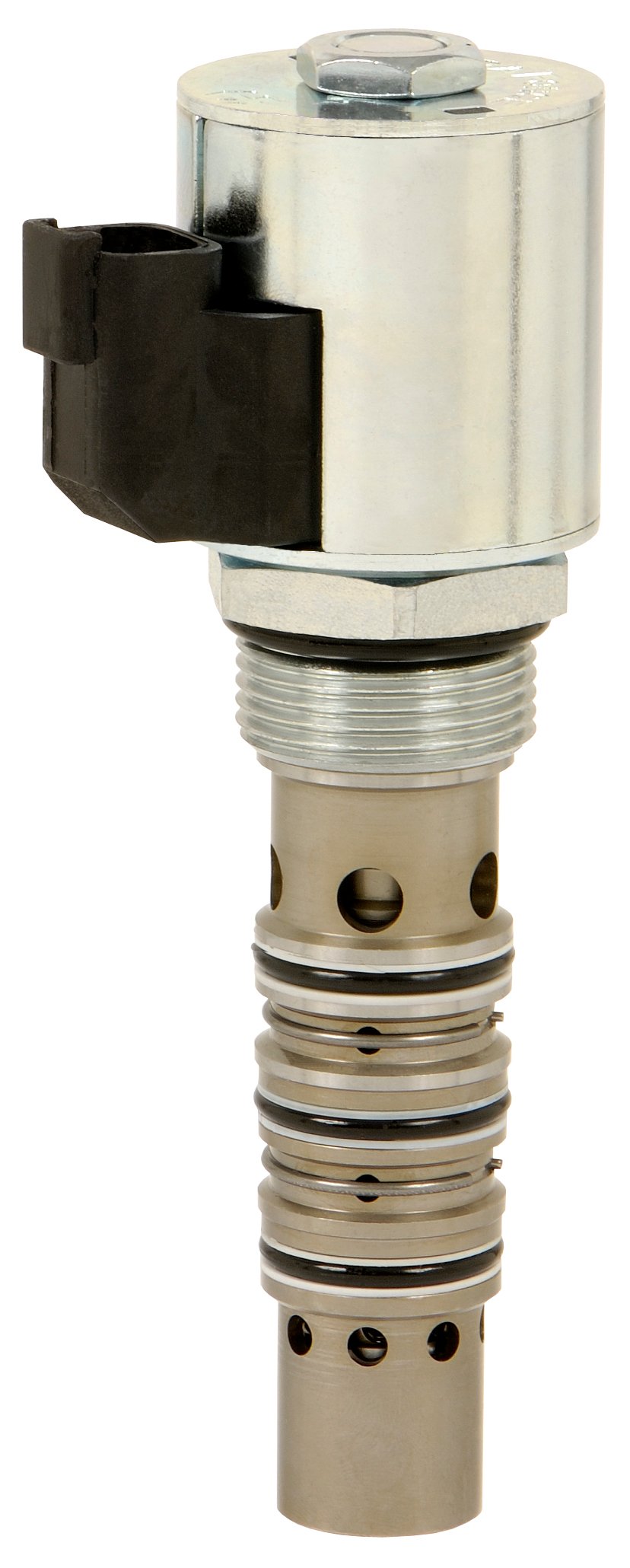
Below is a simplified version of the on/off circuit and the proportional circuit. The trick is that the port logic and cavity details must be exactly the same for both the on/off and the proportional valve. In this example, both valves use the VC12-3 cavity and both have the same port logic of open from port 1 to port 3 with port 2 blocked in the normal condition. And when energized, port 1 opens to port 2 blocking port 3 for the on/off, and proportioning flow from port 1 to port 2 while bypassing what isn’t needed to port 3. In this case, the valve hardware change is roughly $55.00 list per valve.

Dual Coil Polarity Issues Figs. 1, 2, 3


The advantage is that the end users can upgrade their equipment with a field kit from the OEM. As the industry moves toward proportional, and the mix of machines starts to change to more proportional than on/off, the OEM doesn’t have to create a new manifold. The manifold can be preconfigured so that it has commonality of parts, which means lower development cost and service costs, usage of the custom component (manifold in this case) remains consistent, longer machine production life, and so on.

To help you look at this as an option for your equipment development, here is a list of HydraForce on/off valves and their equivalent proportional valve partners having the same cavity detail and port logic:

On/Off Valves
Solenoid Operated
Proportional Valves
Solenoid Operated
SVxx-20
SPxx-20
SVxx-21 SPxx-21
SVxx-22 SPxx-22
SVxx-25 SPxx-25
SVCLxx-30 SPCLxx-30
SVCLxx-31 SPCLxx-32
SVxx-46R SPxx-46R
SVxx-47x SPxx-47x
SVxx-5x SPxx-5x
SV12-33 PV72-31
SV08-33 PV08-31
SV08-31 PV08-30
SVRVxx-26 TSxx-26
SV10-33 TS10-36
Manually Operated  
PR10-36 TS10-36
RV08-20 TS08-20 / TS38-30
RVxx-26 TSxx-26
FRxx-32 ZLxx-30
FRxx-33 PVxx-30
FR12-23 PV72-20 / PV72-21
FR16-20 PV16-23
NV12-30 PV72-33 / PV72-35
MR10-47 SP10-47
MP10-47 SP10-47
Piloted with On/Off Valve or Pressure Reducing/Relieving
SV08-33 EHPR08-33
PDxx-S67 PExx-S67

Some of these conversions are pretty self explanatory, while other might be a bit confusing. Switching the SV08-20 with an SP08-20 is obvious. However, why would you switch from an SV08-33 directional selector to an EHRP08-33 proportional pressure reducing valve? In this case, these two valves would be used in conjunction with a pilot element. In our case the PD16–S67 would be piloted with the SV08-33 selector for the on/off version. If proportional directional control is needed, swapping out the PD with the PE metering element and using the EHPR proportional reducing valve will control pressure against the PE springs, which gives you the proportional movement of the metering spool.

In this case the additional valve hardware cost is less then $100 list.
A great feature for such a small price increase.

Another thing to keep in mind when designing a custom manifold solution for either option: the coils may or may not be identical when going from the on/off to the proportional. (My pricing comments include the coil changes.) In both of my examples, the SV12 spool valve coil was changed to the 70 size coil used on the PV’s and the SV08 coil was changed to an 06 EHPR coil. You can see how planning for adequate spacing of components on the manifold is critical. Check out our free i-Design software for easy manifold customization and configuration flexibility.

Depending on how your machine controllers are configured, a simple “patch’ download for proportional would cost virtually nothing. It’s hard to say where the costing for the electronics would fall. But doing your due diligence in the beginning and planning for this feature will definitely keep the costs down. Adding proportional electronics after the fact will be much more costly. There will, most likely, be some additional costs up front in terms of the controller, the software programming, and the input device, but how will that compare to your readiness when your customers and industry take the leap? Will you be ready?

For more in-depth electronics discussion, contact your local HydraForce expert.

About the Author:

Lisa DeBenedetto is a Regional Manager at HydraForce with more than 20 years of hydraulic experience. She has been with HydraForce for over 16 years. Contact Lisa


Read More

Tags: cartridge valves, proportional valves, Directional Control Valves, directional control valve, hydraulic manifold design, HydraForce, solenoid operated five way valves, manifold design, hydraulic cartridge valves, solenoid valves, proportional directional valves

Suggestions for Cost-Effective Hydraulic Manifold Design

Posted by David Price on Thu, Mar 10, 2011 @ 08:03 AM

Great things come in small packages. In the case of an integrated hydraulic circuit, the smaller, the better. Among the many benefits of a made-to-order block is the ability to achieve a smaller size through a more intelligent design. The 3D layout feature in i-Design will help you conceptualize your design in order to achieve a smaller hydraulic integrated circuit.

In this post I will attempt to clarify the common pricing modifiers that will affect the cost of a hydraulic manifold.

If you are not already familiar with HydraForce's manifold design software called i-Design, you can GO HERE to download a copy today , or contact your local HydraForce distributor to request a copy in disc. HydraForce continues to invest in and refine its i-Design software, and the best part of all: it's FREE!  In 2008, as part of our refinement efforts, HydraForce embarked on a comprehensive research project that included our manifold designers, purchasing department, and our manifold suppliers. The objective of this research was to further refine the scheme we use for pricing manifolds in i-Design by factoring-in the less tangible features of a manifold such as the number of cavities on a surface, the number of ports on a surface, and the mix of large and small cavities. We did this research to develop a better pricing model for our custom manifolds, but the results also offer valuable insight for those of you that design and manufacture their own manifold blocks. Each of the following features has an effect on the complexity and ultimately the cost of the manifold block itself. Unlike a copy of i-Design, spindle time and material are not free.  With the release of i-Design 2.0 in 2008, we included pricing rules for the following manifold modifiers:

• Extra port spacing.
• Cavity mix.
• Number of cavities.
• Number of cavities and/or ports on a surface.
• Ratio of large and small valves.

Extra port spacing for ease of installing fittings is self-explanatory, additional material is required. The cavity mix influences the price because a variety of 08 and 12 size cavities, for example, will require additional cross drills to connect the cavities. Depending on the arrangement, the number of valves or ports on a particular surface can also increase the complexity and the size of the manifold, therefore increasing the cost.
 
Some of these cost factors are not triggered until you lock components and ports to particular surfaces. If we receive an i-Design that includes a manifold layout, but the valves and ports are not locked to particular surfaces or locations, then we interpret the layout as simply a suggestion rather than a necessity. If a particular layout is desired, please use the locking feature in i-Design.
 
Another factor that influences the cost of a manifold is being required to conform to an existing mounting pattern. As you can see from the examples below, the additional material and machining will add cost to the manifold block.

Two manifolds
Two functionally equivalent manifolds
with different mounting hole arrangements.

Original Mounting pattern
Manifold design using the original mounting pattern.

Compact Manifold
More compact version of the manifold.

In conclusion, if you have a manifold design that has a specific mounting configuration that must be adhered to, be aware, it may increase the overall cost of the manifold. If HydraForce needs to conform to a mounting configuration, please use the locking feature in the 2D or 3D layout pages. Being flexible with your manifold requirements gives HydraForce and other manifold designers the freedom to provide you with an optimized, efficient, cost-effective design.

If you would like more information about i-Design,
please contact the i-Design Help Desk.

TO DOWNLOAD A FREE COPY OF i-DESIGN V.3, CLICK HERE


About the Author:

Craig Sinnott is a Regional Manager at HydraForce with more than 16 years of hydraulic experience. Contact Craig

Read More

Tags: cartridge valves, hydraulic manifold design, HydraForce, hydraulic integrated circuit, manifold design

8 Easy Steps to create a 3D Hydraulic Manifold Model

Posted by David Price on Wed, Mar 09, 2011 @ 14:03 PM

When designing a hydraulic manifold, engineers will use a 3D model of a cavity in their CAD/3D modeling software in order to model the proper flow paths of the manifold. Unfortunately, due to various software compatibility issues and inconsistencies in model configuration, the manifold designer has to copy the 3D outline of the cavity, make a 2D outline, then use the 2D outline to create a 3D model. Not only is this process time consuming, but it involves several unnecessary steps.

When designing a hydraulic manifold, engineers will use a 3D model of a cavity in their CAD/3D modeling software in order to model the proper flow paths of the manifold. Unfortunately, due to various software compatibility issues and inconsistencies in model configuration, the manifold designer has to copy the 3D outline of the cavity, make a 2D outline, then use the 2D outline to create a 3D model. Not only is this process time consuming, but it involves several unnecessary steps.


8 Easy Steps to create a 3D Hydraulic Model:

Read More

Tags: manifold design, creating 3D models

Subscribe by Email

Other related info

Sign up for Product news.

describe the image

describe the image

K  SALES TRAINING Image Library Custom Manifold Consultation resized 156

Follow Me

News Ticker

Click Here to see the latest HydraForce News.

Latest Posts

OTHER RELATED INFO

describe the image

describe the image

K  SALES TRAINING Image Library Custom Manifold Consultation resized 156