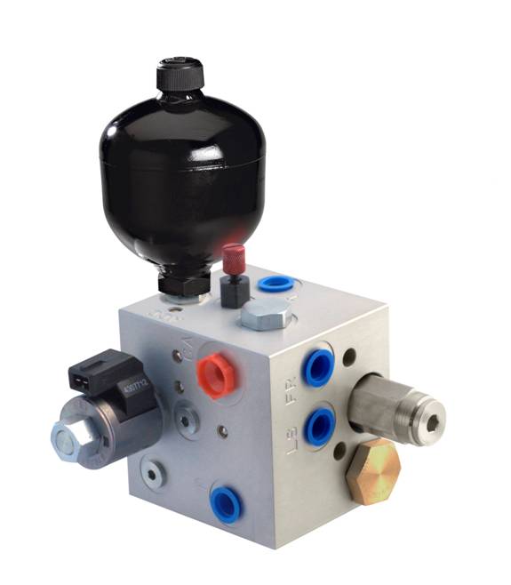
Hydraulic accumulators are widely used in mobile systems in bladder, diaphragm and piston formats. Applications for suspension and ride control have led to an increase in the number of smaller accumulators being mounted directly onto cartridge manifold sub systems. Their many uses include emergency storage, leakage compensation, shock absorption and noise reduction. While it is always a good idea to consult the manufacturer when integrating an accumulator into a manifold, taking the following parameters into consideration can help you avoid system issues. |
|
Read More
Tags:
cartridge valves,
Directional Control Valves,
pressure control valve,
directional control valve,
solenoid valves,
Accumulator Charging Circuit,
unloading pilot valve
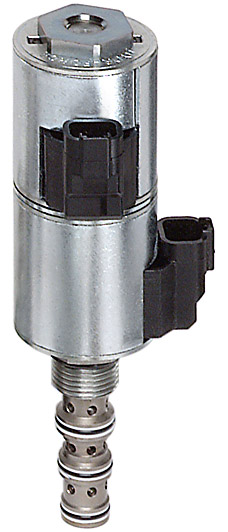
Here at HydraForce our Technical Services department typically receives multiple question daily regarding our Proportional Valves. Common questions include, "What is the proper dither frequency for a particular proportional valve?' and "What coil should I use with this type of system?". Following these five simple rules when applying proportional valves will prevent field failures, reduce valve instability, and ensure that your system performs as desired without having to reach out to a tech service representative.
1. Applying dither to a valve reduces actuator friction and reduces hysteresis. A good rule of thumb is to use 70 -250 Hz dither frequency on all SP, ZL, and PV valves (flow and directional control valves), and 200-300 Hz dither frequency on TS Valves (proportional pressure control valves). Otherwise, at lower frequencies the actuator will follow the dither signal and the valve output will appear unstable.
Read More
Tags:
proportional valves,
Directional Control Valves,
pressure control valve,
proportional flow control valve,
proportional pressure control valve,
Proportional Directional Control Valves
|
While there are many uses for L.S. priority valves, typically they are used to provide priority flow and/or pressure to certain components or functions depending on need. One of the most common uses is to apply them with L.S. steering orbitals.
The two most common types of L.S. steering orbitals (Static and Dynamic) are shown below. We use a static L.S. priority valve (ECxx-42) with a static steering orbital and a dynamic L.S. priority valve (ECxx-43) with a dynamic steering orbital. Notice the direction of the sense flow.
|
 |
|
Static Steering Unit

In a static steering system, the sense flow goes from the steering orbital to the EC valve. The faster you turn the steering wheel, the more flow comes out the work ports.
There are several variable orifices in the steering orbital, which open and close proportionally based on how fast you spin the wheel. In neutral, the sense pressure vents to tank through the steering unit.
|
|
Dynamic Steering Unit

In a dynamic steering system, the sense flow goes from the EC valve to the steering orbital and back to tank through the variable bleed orifice in the steering orbital.
Turning the steering wheel opens the work ports and closes the bleed-off orifice, thus building pressure in the sense line pushing on the EC spool. This directs more oil to the orbital the faster you spin the wheel.
|
| |
|
Most Steering Circuits Utilizing Orbitals Use a Dynamic Setup

Since the steering unit is really just a rotary style variable orifice, using a pre-compensator in conjunction with it makes the steering function compensated. With a given steering RPM, the flow will remain constant regardless of varying load pressure.
The boost orifice needs to be located in the shown position to prevent slow movement of the EC spool when the RV opens, thus preventing a pressure spike.
The objective is for the steering to work perfectly with as little pressure drop as possible, however sometimes we need to fine tune the responsiveness or the maximun steering flow by tweaking a few things.
|
| |
|
Ways to Fine-Tune the Circuit to Optimize Steering Performance

The pressure differential between the EC valve and the L.S. port of the steering unit is called the margin pressure. This pressure differential controls the responsiveness and the maximum steering flow. This is determined by a combination of the bias spring of the EC and boost orifice.
The dynamic L.S. priority valves have two orifices in the spool, one for damping (PP), and the other for feeding (DS) oil to the orbital. The pilot flow to the L.S. port of the steering unit is determined by the spring value and the feed orifice. The spring value is typically either 80 psi or 100 psi, while the orifice is typically between 0.020" and 0.031" Dia., depending on which size EC valve you are using.
You can create any margin pressure you want by simply increasing or decreasing the size of the boost orifice. The smaller the orifice, the higher the margin pressure.
Pressure drop data from a steering unit catalog will help determine what is required to achieve the flow you need. However, the responsiveness or optimum feel is typically determined by an expert operator. By increasing or decreasing the boost orifice, you will be able to fine-tune the responsiveness or feel of the steering wheel.
An increase or decrease of as little as 0.002" Dia. can make a huge difference in the steering feel. Margin pressure that is too low will result in steering that is slow and sluggish. Margin pressure too high will result in jerky steering.
|
| |
| There are many other uses for L.S. Priority Valves as shown below: |
| |
|
Proportional Steering and On/Off Lift Circuit

It is common to use proportional valves instead of steering orbitals to steer many types of equipment. This circuit simply gives priority to steering while allowing the excess flow to lift and lower a cylinder. The EC valve not only gives priority to steering, it also compensates the proportional valve so the same current value will achieve the same flow regardless of load.
|
| |
|
Priority Valve Working with Manual Valve

It is becoming more common to use an EC valve mounted to the inlet of a manual valve to give priority to certain functions while also limiting the maximum flow and pressure to those functions.
|
| |
|
Typical Priority-on-Demand
Flow Control Circuit

Most uses of the L.S. Priority Valves are for flow control. By sensing downstream of a fixed or variable orifice, you can compensate the circuit. The needle valve shown above could be any one of a number of components such as a ball valve, proportional valve, on/off valve or a simple orifice.
|
|
Pressure Control Valve

Many people don't realize you can use an
ECxx-42 or ECxx-43 to create a pressure control. Think of this as a pressure reducing valve with an excess flow port. The valve will modulate to maintain the spring value in the priority (CF) leg regardless of flow and/or the downstream pressure and flow in the bypass leg. Higher spring pressures can be achieved by using an ECxx-43 and boosting the sense line with an orifice or relief valve.
|
Do you have another Priority Valve Application?
Do you have any questions about any of the circuits I describe here?
Shoot me an email if you’d like to share your application or ask a question.
About the Author:

Scott Parker is a Senior Application Engineer at HydraForce.
He’s been developing Hydraulic Systems for 20 years. Contact Scott
Tags:
cartridge valves,
Load Sensing,
Priority Valves,
Hydraulic Steering Circuits,
Load Sense Priority Valves,
benefits of cartridge valves,
pressure control valve
A pressure compensator maintains a constant pressure drop across a metering device regardless of the load induced pressure on the function. There are only two types of compensation methods used in hydraulic flow control functions. These are pre- and post-style compensation. Pre and Post refer to the position of the pressure compensating element relative to the metering element. A pre-style pressure compensator is positioned upstream of the metering element (a proportional valve) and a post-compensator is positioned downstream of the metering element. There is also a sub-category of these, which adds load sharing (this is sometimes called flow sharing). Using current cartridge valve technology, load sharing is limited to post-compensation circuits.
|
 |
Tags:
cartridge valves,
proportional valves,
pressure control valve,
directional control valve,
hydraulic cartridge valves,
pressure compensators,
pressure compensation,
Piloted,
Spool-Type Logic Element,
proportional directional valves,
pre-compensated hydraulic systems,
post compensated hydraulic systems
| Someone recently joked with me that I’ve never created a circuit that didn’t have at least one Logic Valve in it. HydraForce model numbers for these valves begin with the prefixes EP, EPFR and EV. Typically, these valves are piloted-closed, vented-open, or used as pressure compensators or regulators. I use them often because they are versatile, and they have low pressure-rise and pressure-drop characteristics. |
 |
On our catalog pages for these valves, we describe them as: “hydraulic directional element, with multifunction potential when used with other directional, pressure, or flow control devices.” Talk about a vague (albeit true) statement. So, to demystify this situation a little, I started to think about all the different ways spool-type logic valves can be used in integrated circuits. I’ve sketched up some generic circuits that show different ways in which we use spool type logic valves:
Tags:
cartridge valves,
pressure control valve,
logic valves,
pressure compensators,
Bypass Pressure Compensator,
Sequence Valve,
Accumulator Charging Circuit,
cartridge
| Someone recently joked with me that I’ve never created a circuit that didn’t have at least one Logic Valve in it. HydraForce model numbers for these valves begin with the prefixes EP, EPFR and EV. Typically, these valves are piloted-closed, vented-open, or used as pressure compensators or regulators. I use them often because they are versatile, and they have low pressure-rise and pressure-drop characteristics. |
|
On our catalog pages for these valves, we describe them as: “hydraulic directional element, with multifunction potential when used with other directional, pressure, or flow control devices.” Talk about a vague (albeit true) statement. So, to demystify this situation a little, I started to think about all the different ways spool-type logic valves can be used in integrated circuits. I’ve sketched up some generic circuits that show different ways in which we use spool type logic valves:
Tags:
cartridge valves,
pressure control valve,
logic valves,
pressure compensators,
Bypass Pressure Compensator,
Sequence Valve,
Accumulator Charging Circuit,
cartridge

The proper performance of a hydraulic system is usually attributed to major components such as the motor, pump and valves. However, there is another unsung component that contributes equally to a system's overall performance: the orifice. In most traditional main hydraulic valves, orifices are built into the casting or dismounting components mold by the component’s constructors. In a cartridge valve manifold (otherwise known as a hydraulic integrated circuit), you start with a blank sheet of paper. Therefore, it is important to know where and when an orifice can change the performance of your system. |
|
The orifice is one of the most versatile components that we can add in our hydraulic circuit. The orifice can be used to limit the amount of oil in one part of our system, to bleed a pressure line to tank, or to transform a nervous and aggressive circuit into an efficient and highly controlled one. Often times the orifice has to simultaneously manage a very small amount of oil, control a dynamic flow rate and dump a system’s compensator. In many applications -- especially for hydrostatic transmissions -- it is important to control the dynamic pressure of the system to avoid pressure spikes and pressure ripple.
Read More
Tags:
Load Sensing,
pressure control valve,
proportional flow control valve,
combine pressure control valve and flow regulator,
hydraulic integrated circuit,
Orifices