When designing a hydraulic system, you want to optimize your design for minimal pressure drop. Savvy system designers have found that using a custom manifold with the right combination of cartridge valves is one way to optimize a system. When using this approach, it is important to correctly size your valves, drillings, and flow paths within the manifold. It is just as important to “right-size” the hydraulic hose and pipe connecting the manifold to the rest of the installation. Hose and tubing need to be the right diameter, length, smoothness and shape to handle the demands of the pressurized hydraulic flow. Undersized hose or tube can cause turbulent flow and excessive heat buildup. Over-sized hose or tube can add cost, size and weight to a system and decrease the rate of flow.
To understand what “right-sizing” means in terms of hydraulic hose and tube, you must first understand the nature of fluid and friction. Whenever fluid flows, there is a loss of mechanical energy to overcome viscous forces within the fluid. In a hydraulic system, this loss is seen as a pressure drop in the direction of flow.
Each component within the hydraulic system will contribute toward the pressure drop, i.e. cartridge valves, tubing, fittings, hoses, filters etc. This lost energy is dissipated as heat energy in the oil.
Frictional losses in pipework are mainly dependent upon:
-
Length of pipe
-
Cross-sectional area of pipe
-
Roughness of pipe surface
-
Number of pipe bends
-
Velocity of flow
-
Viscosity of fluid
The total allowable pressure drop of the hydraulic system must be chosen with care, as the power loss is a product of the system flow rate and pressure drop. This is an efficiency loss that has to be balanced against the cost of larger pipework/hoses and fittings. The wasted energy is dissipated as heat energy in oil, which may lead to cooling problems and shortening of the oil life.
Pressure losses in pipework will depend upon the flow condition. There are two distinct flow conditions:
-
Laminar Flow and
-
Turbulent Flow.
Laminar flow is the condition when the fluid particles travel smoothly in straight lines, the inner-most fluid layer travels at the highest speed and the outer-most layer at the pipe surface doesn’t move, as shown in Figure 1.
Figure 1 – Laminar Flow
Turbulent flow has irregular and chaotic fluid particle motions, such that a thorough mixing of the fluid take place, as shown in Figure 2. Turbulent flow is usually not desirable, as the flow resistance increases and thus the hydraulic losses increase.
Figure 2 – Turbulent Flow
The Right Calculations
To determine the right size of hydraulic piping, you must first do the right calculations for the nature of the hydraulic flow in your system.
Osborne Reynolds discovered that the flow condition depended upon the mean flow velocity, the diameter of the pipe and the kinematic viscosity of the fluid, formula 1.
Q = Flow (m3/s)
d = Pipe internal diameter (m)
ν = Kinematic Viscosity (m2/s)
A Reynolds number of 2000 or under is deemed to be laminar flow. A Reynolds number above 3000 indicates turbulent flow.
Pressure loss in straight pipe can be calculated using Poiseuille’s equation (for laminar flow only). See Formula 2.
ΔP = |
128 μ L Q |
|
|
|
|
Π d4 |
|
Formula 2 |
|
A more general equation used for turbulent flow and laminar flow is D’Arcy equation. See Formula 3.
ΔP = |
4f |
L |
|
ρ U2 |
|
|
|
|
|
d |
|
2 |
|
Formula 3 |
|
ΔP = Pressure Loss (Nm-2)
F = Pipe Friction Factor
L = Pipe Length (m)
D = Pipe internal diameter (m)
ρ = fluid density (kg m -3)
U = Fluid mean velocity (ms-1)
The friction factor (f) depends upon the nature of the flow in the pipe. The most convenient form of depicting friction factors are from a Moody Diagram. However for hydraulic systems it is often assumed the pipe conditions are smooth.
A quick and easy and more common method of determining pipe/hose sizing, is to calculate the diameter size based upon recommend fluid velocities. See Table 1.
Line Type |
Recommend Mean Velocity m/s |
Suction & Case Drain Lines |
0.5 to 1.5 |
Return Lines |
2 to 4 |
Pressure Lines |
3 to 5 |
Table 1 – Recommend Mean Fluid Velocities
Based upon using the mean fluid velocities, the appropriate hose/pipe diameter is determined using Formula 4.
V= |
Q x 21.22 |
|
|
|
|
d2 |
|
Formula 4 |
|
Rearrange the formula to get:
d= |
√ |
Q x 21.22 |
|
|
|
|
|
V |
|
Formula 5 |
|
d = Diameter (mm)
Q = Flow (lpm)
V = Fluid Velocity (m/s)
This quick check calculation is useful to ensure that potential pressure drop and energy loss due to hose/pipework is not excessive when designing your manifold installation. For critical long runs of pipe or hose, the pressure losses should be checked using Poiseuille’s or D’Arcy equations as briefly discussed earlier.
Don’t let the wrong size of hydraulic hose or pipe keep your hydraulic system from reaching its maximum efficiency. Do the right calculations, and specify the right size of hydraulic hose and tubing to keep your installation at optimum working pressure.

Read More
Tags:
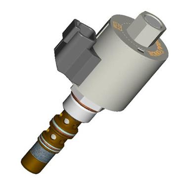
cartridge valves,
hydraulic circuit,
hydraulic integrated circuit,
manifold design,
hydraulic cartridge valves,
proper installation of cartridge valves,
efficient manifold design
With Programmable Electronic Controls becoming more prevalent in many hydraulic systems it’s a good time to look at one alternative to Proportional Direction control made possible with the advent of electronic closed loop control. |
|
Read More
Tags:
cartridge valves,
proportional valves,
Directional Control Valves,
proportional pressure control valve,
solenoid operated four way valves,
directional control valve,
hydraulic manifold design,
ecu's,
hydraulic circuit
A cartridge valve’s function is represented with an ISO standard hydraulic symbol that characterizes the function that the valve performs. In our many product pages, you can find many unusual valves with very peculiar and complex hydraulic symbols that appear to contain an entire small hydraulic circuit. In this post I will discuss the principle beyond combining cartridge valves and provide a few practical examples that may help you save money when you are designing a hydraulic circuit. |
|
The idea to develop Multifunction Valves came from our engineers noticing that particular combinations of valves were used over and over again in standard hydraulic circuits. For example, a 2-way, 2-position SP proportional valve is typically paired with a pressure compensator to provide pressure compensated flow control. This particular example drove the development of the PV Proportional Flow Control family of valves, which include the flow control and pressure compensator inside the same cartridge. There are many other multi-function options, including the SPCL, SVCL, SVRV, EPFR, FRRV, and others).
Read More
Tags:
cartridge valves,
benefits of cartridge valves,
Directional Control Valves,
proportional flow control valve,
hydraulic circuit,
manifold design