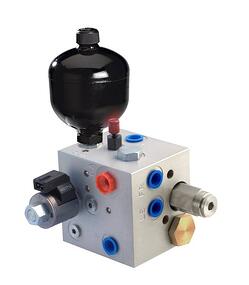
Hydraulic accumulators are widely used in mobile systems in bladder, diaphragm and piston formats. Applications for suspension and ride control have led to an increase in the number of smaller accumulators being mounted directly onto cartridge manifold sub systems. Their many uses include emergency storage, leakage compensation, shock absorption and noise reduction. While it is always a good idea to consult the manufacturer when integrating an accumulator into a manifold, taking the following parameters into consideration can help you avoid system issues. |
 |
High Temperature Considerations
The effects of high temperatures and duty cycle in some mobile applications can easily be overlooked. While the OEM normally takes responsibility for selecting the accumulator, the hydraulic sub system designer may be the first port of call when things go wrong. So it’s best to be forearmed.
There are several reasons why normal gas temperatures are underestimated. The gas temperature is affected by ambient air, ambient fluid and rate of charge/discharge. Therefore, ignoring any of these factors will increase your chances for system malfunction:
-
Ambient of a piston type accumulator may be more related to atmospheric temperature
-
Ambient of a bladder or diaphragm accumulator may be more related to fluid temperature
-
The fluid at the accumulator membrane may not be well circulated within the system, further increasing the temperature.
-
Rapid charging raises the gas temperature. The temperature will settle back given time, but it depends on how quick the charge rate was and how soon the next cycle begins.
-
An accumulator location could also be innocently changed after machine tests have been completed.
The first general rule when applying an accumulator into a is that the precharge pressure should be 10% below the minimum working pressure. Don’t rely on this.
The accumulator manufacturer will normally set this pressure at 20 deg C unless otherwise specified. Bear this in mind for mobile applications where vehicles could be in high ambient temperatures, where fluid temp is high or where the accumulator is near the engine compartment or exhaust system.
A high precharge is best for optimum storage but temperature rise could elevate this pressure (P0) to above the minimum working pressure P1.
Result:
-
Calculated stored volume is vastly reduced
-
Recharging cycle rate is increased, further raising temperature and hence ‘locking in’ the failure mode
-
Unloading valve fails due to excessive cycling.
-
Damage can occur where the bladder repeatedly strikes the port opening. (LS10-41 can be used to protect against such failures in critical applications)
|
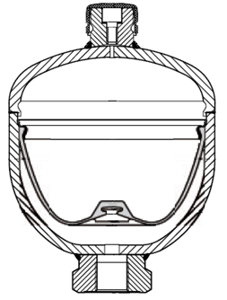
Typical Diaphragm Accumulator |
Calculations:
The P*V/T relationship can be used to show this, where V is constant (Precharge volume is always the accumulator volume). Remember that T is degrees Kelvin so 20 c = 293 deg K.
For example, if the gas temperature rises to 60 deg C then the precharge pressure rises by 333/293, an increase of 13.65%. This encroaches into the minimum working pressure area so the system would fail if precharge had been arbitrarily set 10 % below minimum working pressure. The precharge should therefore be specified at the higher temperature, or lowered to compensate for the temperature rise. Use this ratio as a quick check (Precharge multiplier = (max temp deg C +273)/ (20 deg C +273)
The deviation is therefore greater for higher gas temperatures. It’s easy to set the precharge lower just to be safe but this does significantly reduce available stored volume. The circuit below shows a practical example where a number of operations of release cylinder 1 & 2 may be required in the event of pump/engine failure. The side notation shows all calculations including consideration to temperature rise. Low leakage solenoid valves like the SV38-38 and load sensing poppet valves type SVCL’s are ideal in these applications to minimize leakage.
| Low Leakage Accumulator Circuit (to download this circuit, Click Here.) |
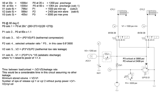
The UP10-31 unloader valve has optional load/unload ratios of 60%, 70% and 80%, providing versatility to correct for unexpected temperature extremes where fixed differential pressure switches could result in higher cycling.
Duty Cycle and maximizing the differential from P3 to P2 :
Don’t forget to consider the cycle life in accumulator applications. It’s easy to underestimate how quickly 100,000 cycles can be attained. This can be much sooner than anticipated due to miscalculation, if temperature rise has not been considered, or where internal leakages may increase with system age. The different ratios of the UP10-31 valve allow the system to be optimized for minimum cycling. Fixed differential pressure switches could result in higher cycling.
Holding check valve and settling temperature:
A good, low leakage check valve such as CVXX-20 is important to extend the cycle time. When a system is charged reasonably quickly the gas temperature will rise then settle back exponentially to ambient (if left long enough). The retained pressure will therefore fall during this period (without system leakage). This effect is often overlooked and the holding check valve may be incorrectly diagnosed to be leaking. Reducing the rate of charge alleviates this symptom and holds a higher pressure longer.
The concepts discusssed above are by no means the only things to consider when applying accumulators in a manifold, but they are good place to start.
About the Author:
Jim Eaton is an Applications Engineer at HydraForce LTD in the U.K. He has been designing hydraulic systems for over 30 years.


